Robotics / Embedded
FPGA-Controlled Hexapod Robot
FPGA-based PWM generation and push-button control for the Spider robot, progressing from a single servo to independent control of three joints on one leg.
01 / Overview
Project at a glance.
From a clock signal to independent servo control: adjustable PWM, stored position values, bounded updates, and joint selection.
02 / System approach
How the pieces connect.
A simplified view of the functional path. Original artifacts and detailed evidence follow below.
- 01Position input
- 02Bounded update
- 03PWM generator
- 04Servo joint
Building the servo-control foundation
EECE 2160, Embedded Design: Enabling Robotics, is an integrated lecture and lab course connecting digital design, object-oriented programming, Linux, and software control of physical devices. The servo work below documents its FPGA hardware-control portion.
Completed with Preeth Somanchi for EECE 2160, Embedded Design: Enabling Robotics, this work developed FPGA-based control of the Spider robot’s servo-driven joints. Lab 4 introduced adjustable PWM generation; Lab 5 extended the design to incremental control of three joints on one leg.
Platform and tools
DE10-Nano SoC · Intel Quartus Prime Lite · FPGA logic · PWM
Project record
Lab 4 report: October 25, 2024
Lab 5 report: November 8, 2024
Individual responsibilities within the partnership: to add.
From a clock to controlled movement
Generating the PWM signal
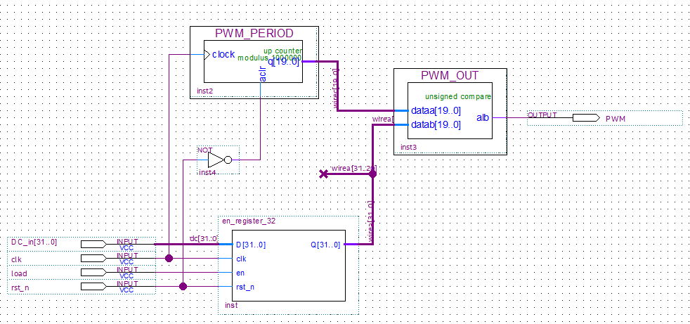
The Lab 4 design uses a 50 MHz clock and a 1,000,000-cycle counter for a 20 ms PWM period. A 32-bit register stores the pulse-width value, and a comparator determines how long the output remains high. The report calculates 30,000, 75,000, and 120,000 clock cycles for 0.6 ms, 1.5 ms, and 2.4 ms pulses.
Loading a target position
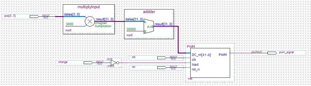
A four-switch input is scaled by 3,000 and offset by 30,000. The load button commits the new value to the PWM register, so changing switches alone does not immediately move the servo.
Adding incremental joint control
Lab 5 introduces an add/subtract module that changes the stored duty cycle in steps of 3,000 counts. Comparator and multiplexer logic reject updates outside the configured bounds and select a 75,000-count position after a reset state. A button-release pulse triggers the update.
Selecting joints independently
The SpiderOneLeg design combines the PWM and update logic for three servos. Enable switches select which joints respond, while a direction input selects increment or decrement. The report describes reset returning all joints to their expected position regardless of the enable switches.
Implementation and control decisions
Translate position into clock counts
At 50 MHz, each clock tick is 20 ns. A 20 ms PWM period therefore spans 1,000,000 ticks. Lab 4 derives the position relationship as counts = angle in degrees × 500 + 30,000, and maps the four-switch value using counts = switch value × 3,000 + 30,000.
The switch mapping spans 30,000–75,000 counts, or 0.6–1.5 ms high pulses. This covers the lower half of the report’s nominal 0.6–2.4 ms servo range.
Store the command before changing the output
An enabled 32-bit register holds the requested pulse width. The period counter provides a repeating time base, and the comparator keeps the PWM output high while the count is below the stored width. A separate load input makes position changes deliberate rather than immediately following every switch change.
Generate one update on button release
Lab 5 uses D-flip-flop-based press detection so a press-and-release event triggers an update pulse. This avoids repeatedly applying the position increment while the button remains held. The report describes an active-low button and release-triggered behavior; it does not establish a separate mechanical debounce implementation.
Reject invalid updates
A 32-bit add/subtract block proposes the next width. Comparators determine whether the candidate lies inside the configured limits, and a multiplexer selects the candidate, the unchanged current value, or the 75,000-count reset position. The bounds therefore constrain the stored command rather than relying on the operator to stop at the right point.
Replicate control for three joints
The final SpiderOneLeg design shares the board clock, update button, reset button, and direction switch across three channels. Each channel has its own enable switch, allowing one joint or a selected combination of joints to move. Reset acts across all joints regardless of enable selection.
Technical challenges and reported lessons
Human input and continuous logic
The FPGA clock runs continuously, while a user expects one movement command per button action. Storing target values and generating an update on release connects those two time scales.
Motion limits
The report’s 98,000-count test checks both directions near a boundary: decrement is accepted, while increment is rejected. This tests the decision logic as well as the arithmetic.
Independent and shared control
Joint-enable inputs allow selective movement, while shared reset restores a known position. The hardware tests exercised all-enabled movement, selective movement, and reset with enable switches in different states.
From simulation to movement
Waveform checks verified the update module before the full design was uploaded to the robot. The reports connect registers, counters, comparators, and multiplexers to observable servo movement.
A 3,000-count step corresponds to 60 µs at the documented 50 MHz clock. The Lab 5 prose gives a conflicting conversion; this case study uses the clock-count calculation.
Original design artifacts
These schematics and waveform captures come from the archived lab work.
PWM generator
Switch-controlled servo position
Duty-cycle update simulation

Documented testing
The following outcomes are reported in the submitted lab write-ups. They describe the archived tests, rather than new tests performed for this website.
| Test | Reported observation |
|---|---|
| Switch-controlled position | The leg responded to several switch settings and waited for the load button before updating. |
| Reset input of zero | Waveform output selected the 75,000-count reset position. |
| 98,000-count boundary case | Decrement produced 95,000; increment retained 98,000 because 101,000 exceeded the configured limit. |
| 65,535-count interior case | Increment produced 68,535 and decrement produced 62,535. |
| Three-joint hardware control | All enabled joints incremented. With the second joint disabled, only the first and third decremented. |
| Hardware reset | All joints returned to the expected position regardless of enable settings. |
Connecting hardware and software
The archive also contains later C++ labs covering memory-mapped I/O, LEDs, switches, and push buttons on a DE1-SoC. These provide related embedded-software context; the supplied material does not yet document their integration into full-robot motion control.
Design decisions
Stored duty-cycle values separate position selection from movement. Enable inputs allow joints to be controlled independently, and bounds checks constrain incremental updates.
Further project details
To add: full-robot coordination, walking sequences, C++ integration, individual contributions, and lessons learned.
Source material
Based on the jointly authored Lab 4 and Lab 5 reports and their archived schematic and waveform images.